Knock-knock- a door or window sensor prototype in (Micro)Python on the Pico, D1 mini and Pi Zero
Jump to: Pico – D1 mini – Pi Zero
Raspberry Pico
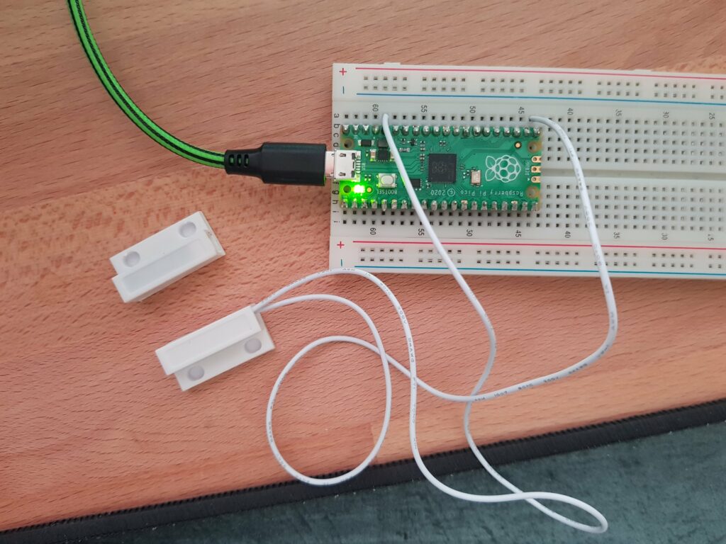
A short Python implementation of a magnetic switch turning on a LED when it is not connected (e.g. window is opened). For simplicity reasons I used the builtin LED on the Pico.
from machine import Pin
from time import sleep

led = Pin(25, Pin.OUT)
sensor = Pin(16, Pin.IN, pull=Pin.PULL_DOWN)

while True:
    led.value(1) if sensor.value() == 0 else led.value(0)
    sleep(0.5)
You have to use the pull=Pin.PULL_DOWN parameter for the input pin (sensor). With the while True loop, the code runs forever and checks the switch state every .5 seconds and turns the led on if it is disconnected or off if it is connected.
If you have a Pico W, you could use the sensor input as trigger to send a wifi signal to a IoT cloud service or your mqtt server for further processing.
D1 mini
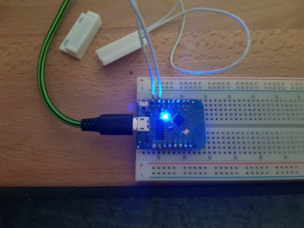
Pretty much the same on the D1 mini – I am using the D1 mini lite here, but that doesn’t matter. I flashed the current MicroPython. Get it here. How to flash it with Thonny.
As the D1 has no software pull down, we have to use the D8 pin(15), which has a built in 10k pull down resistor (thanks lazyzero). I also used the onboard LED of the D1 mini (pin 2).
from machine import Pin
from time import sleep

led = Pin(2, Pin.OUT)
sensor = Pin(15, Pin.IN)

while True:
    led.value(1) if sensor.value() == 1 else led.value(0)
    sleep(0.5)
The only difference are the GPIO numbers and the missing pull down parameter for the sensor. If you want to use another pin, you have to install a physical pull down resistor as seen below.
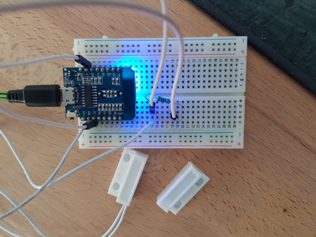
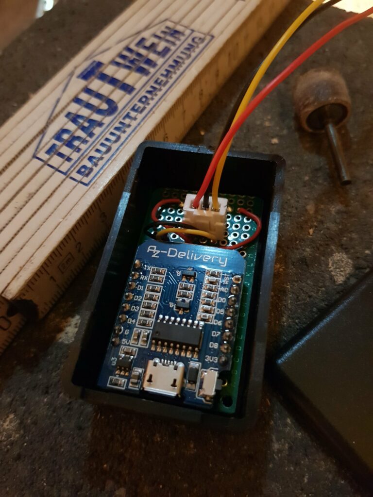
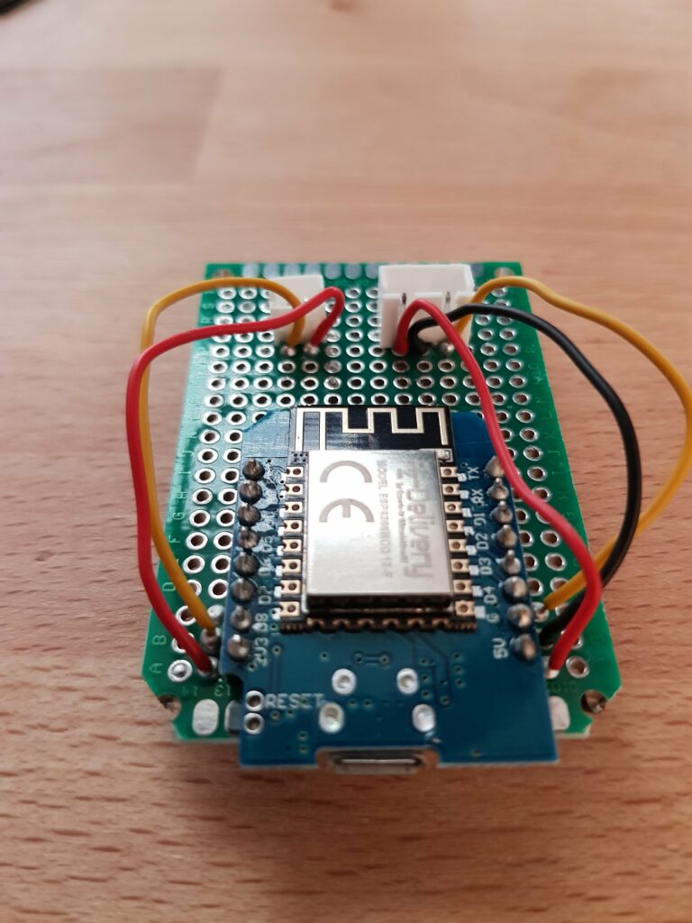
The magnetic switch is connected to 3v3 and row 14 on the breadboard. The white cable in the middle of row 14 is connected to D7 (GPIO 13). The resistor above it short circuits to the ground connection in row 18. 10k Ohm works fine, as well as the 56k Ohm in the picture. Without the ground connection the input pin would always register as high and therefore not show a changed state of the magnetic switch. Without the resistor in the ground connection the D1 would reboot.
The code only changed slightly, because another input pin was used:
from machine import Pin
from time import sleep
led = Pin(2, Pin.OUT)
sensor = Pin(13, Pin.IN)
while True:
led.value(1) if sensor.value() == 1 else led.value(0)
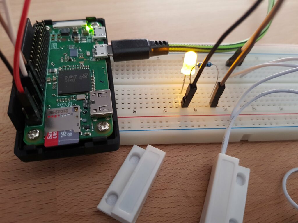
sleep(0.5)Raspberry Pi Zero
Pi Zero pinout | PyCharm | gpiozero | Thonny
A little more effort is needed for the preparation to do this on the Raspberry Pi Zero, but the code remains pretty much the same – as expected. To my knowledge there’s no builtin LED on the Pi Zero you can use for this, so you have to build a small prototype setup on a breadboard or sth. comparable. I connected a standard LED to the GPIO 17 with a 330 Ohm resistor and to the ground. The magnetic switch was connected to GPIO 4. The Pi Zero uses the gpiozero module instead of the machine module in MicroPython. The code looks a little different as in the gpiozero module there are many devices that derive from Input- or OutputDevice and therefore only the pin number is mandatory, but basically it’s the same.
from gpiozero import LED, DigitalInputDevice
from time import sleep
led = LED(pin=17)
sensor = DigitalInputDevice(pin=4)
while True:
led.on() if not sensor.is_active else led.off()
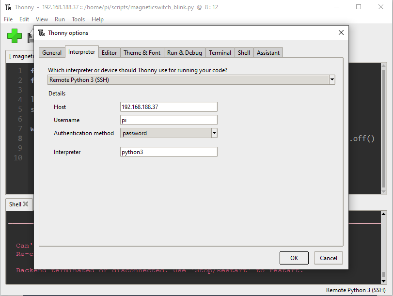
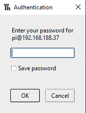
sleep(0.5)As I am using a headless wireless installation on the Pi Zero I couldn’t just edit the .py file on the desktop, but used PyCharm on my desktop computer, installed the gpiozero module and adapted the code lines from the previous examples. To save it on the Pi Zero the Thonny feature to connect to a remote python interpreter came in handy. Copied and pasted the code like a pro and ran it with Thonny (see screenshots below).